


Industry
 Num:74
 See:2784
2021-06
23
[Dry goods] MOS tube driver circuit analysis
MOS tube driver has a variety of ways, there are special driver chip driver, but also useful for other devices to build the driver, the following is to explain the current more popular driving methods.
The simplest way to do this is to drive power management chips directly. Power chips have the ability to drive MOS tubes directly, only when this drive is applied.
1. We need to pay attention to the Sink/Source Capability in our chip specifications, and the corresponding parameters of different chips are different.
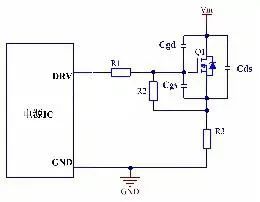
2. Understand the parasitic capacitors of MOSFET, such as CGD and CGS in the figure. When we turn on the MOS tube, we are just charging CGD and CGS. Generally, the MOS tube current used for low-power power supply is not very large, and it is possible to use the chip to drive directly. Some chips indicate in the specification book that the chip can do more than the maximum W power supply. The circuit below is directly driven by the chip through the resistor, on and off at the same speed.
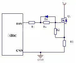
We have a lot of time in order to make the opening of the speed slow down, turn off the speed of change quickly, this is because the shut off when the voltage is generally higher than the opening, the words off loss than the opening of the loss is big, in order to solve this problem, I can control speed is reduced, so that it can reduce speed off. How to do this is shown below. From the following figure, it can be seen that when the MOS tube is turned on, R1 and R4 are current limiting, and then the capacitor of the MOS tube is charged. When it is turned off, the voltage above the resistance of R4 is clamped at 0.7V (here it is thought that the VF of the diode is 0.7V). When the voltage is greater than 0.7V, the current flows through the diode and then discharges in series with R1. It reduces the driving resistance, such as MOS tube quickly shut off, reduced the turn-off losses, this circuit, the general R1 and R4 resistance parameters matching, are generally less than R4 R1, R1 is 22 Ω, for example, the parameters of the R4 is 47 Ω, of course, this parameter is not fixed, can change, the different parameters of MOS tube is not the same. Although it speeds up the turn-off speed, it is necessary to increase the driving ability of the power chip. Some chips with insufficient capacity can be realized by adding PNP triodes.
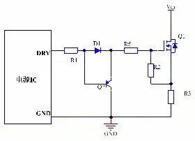
The following figure is to increase the driving circuit of transistor, MOS opened or let chip to direct drive, shut off when the discharge through triode, make triode working in discharge, let the triode be current to control the ec current discharge of charge of the gate capacitance MOS tube, ec current is through be current amplification, As long as the CE current of the triode is enough, the power IC required to turn off capacity will be much smaller, solve the problem of turning off speed open, but also solve the problem of insufficient IC drive capacity.
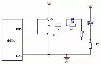
Solve the ability to shut off, for some low power supply, perhaps the MOS tube current is larger, drive capacity is very big, there are even more than the power supply in parallel, etc., this time the power chip may direct drive MOS tube ability is not enough, at the same time there will be a chip and MOS tube distance is far, if direct driving chip, The line sense on PCB is also relatively large, so triodes can be added to drive MOS when it is turned off, and triodes can also be added to drive MOS when it is turned on, so that the driving energy of the chip is greatly reduced. As shown in the picture below, we added two audions, which is a push-pull circuit also known as a totem pole circuit. He has two big benefits.
1. Amplify the drive energy of the chip, so that multiple MOS tubes can be driven at the same time, and all of them have enough energy, so that most of the power consumption of the drive is distributed to the totem pole, so that the power consumption of the chip is reduced and the problem of high chip temperature is avoided.
2. The totem pole circuit can be moved at will when the PCB drawing board, so that it can be close to the MOS tube, so that the line sense on the driving circuit of the MOS tube opening and closing is very small, so as to avoid some unnecessary misactions.
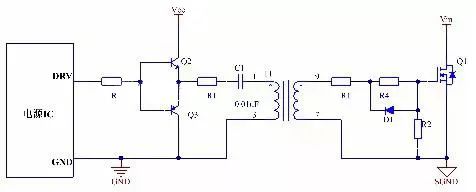
The above several circuit with chip is to MOS tube, sometimes there will be no common ground, such as half bridge on tube MOS tube, this is not altogether to MOS driver, will use the isolation transformer, for isolating transformer application many times is the following circuit, is to increase the isolation transformer, at the same time increase the RC filter circuit, a The purpose of R1 is to restrain the parasitic inductor on PCB board from forming LC oscillation with C1, the purpose of C1 is to separate DC through AC, and at the same time to prevent the saturation of magnetic core.
The simplest way to do this is to drive power management chips directly. Power chips have the ability to drive MOS tubes directly, only when this drive is applied.
1. We need to pay attention to the Sink/Source Capability in our chip specifications, and the corresponding parameters of different chips are different.
2. Understand the parasitic capacitors of MOSFET, such as CGD and CGS in the figure. When we turn on the MOS tube, we are just charging CGD and CGS. Generally, the MOS tube current used for low-power power supply is not very large, and it is possible to use the chip to drive directly. Some chips indicate in the specification book that the chip can do more than the maximum W power supply. The circuit below is directly driven by the chip through the resistor, on and off at the same speed.
We have a lot of time in order to make the opening of the speed slow down, turn off the speed of change quickly, this is because the shut off when the voltage is generally higher than the opening, the words off loss than the opening of the loss is big, in order to solve this problem, I can control speed is reduced, so that it can reduce speed off. How to do this is shown below. From the following figure, it can be seen that when the MOS tube is turned on, R1 and R4 are current limiting, and then the capacitor of the MOS tube is charged. When it is turned off, the voltage above the resistance of R4 is clamped at 0.7V (here it is thought that the VF of the diode is 0.7V). When the voltage is greater than 0.7V, the current flows through the diode and then discharges in series with R1. It reduces the driving resistance, such as MOS tube quickly shut off, reduced the turn-off losses, this circuit, the general R1 and R4 resistance parameters matching, are generally less than R4 R1, R1 is 22 Ω, for example, the parameters of the R4 is 47 Ω, of course, this parameter is not fixed, can change, the different parameters of MOS tube is not the same. Although it speeds up the turn-off speed, it is necessary to increase the driving ability of the power chip. Some chips with insufficient capacity can be realized by adding PNP triodes.
The following figure is to increase the driving circuit of transistor, MOS opened or let chip to direct drive, shut off when the discharge through triode, make triode working in discharge, let the triode be current to control the ec current discharge of charge of the gate capacitance MOS tube, ec current is through be current amplification, As long as the CE current of the triode is enough, the power IC required to turn off capacity will be much smaller, solve the problem of turning off speed open, but also solve the problem of insufficient IC drive capacity.
Solve the ability to shut off, for some low power supply, perhaps the MOS tube current is larger, drive capacity is very big, there are even more than the power supply in parallel, etc., this time the power chip may direct drive MOS tube ability is not enough, at the same time there will be a chip and MOS tube distance is far, if direct driving chip, The line sense on PCB is also relatively large, so triodes can be added to drive MOS when it is turned off, and triodes can also be added to drive MOS when it is turned on, so that the driving energy of the chip is greatly reduced. As shown in the picture below, we added two audions, which is a push-pull circuit also known as a totem pole circuit. He has two big benefits.
1. Amplify the drive energy of the chip, so that multiple MOS tubes can be driven at the same time, and all of them have enough energy, so that most of the power consumption of the drive is distributed to the totem pole, so that the power consumption of the chip is reduced and the problem of high chip temperature is avoided.
2. The totem pole circuit can be moved at will when the PCB drawing board, so that it can be close to the MOS tube, so that the line sense on the driving circuit of the MOS tube opening and closing is very small, so as to avoid some unnecessary misactions.
The above several circuit with chip is to MOS tube, sometimes there will be no common ground, such as half bridge on tube MOS tube, this is not altogether to MOS driver, will use the isolation transformer, for isolating transformer application many times is the following circuit, is to increase the isolation transformer, at the same time increase the RC filter circuit, a The purpose of R1 is to restrain the parasitic inductor on PCB board from forming LC oscillation with C1, the purpose of C1 is to separate DC through AC, and at the same time to prevent the saturation of magnetic core.
Share


- About
- Company Profile
- Company Honor
- Products
- FIELD EFFECT TRANSISTOR
- SCHOTTKY DIODES
- ULTRAFAST RECOVERY POWER RECTIFIER
- SIC SCHOTTKY DIODES
- Silicon carbide MOSFET
- Follow
-
Address:Room 402-404,Qianhai ChengJin Building,Moon Bay Boulevard, Nanshan District,Shenzhen
Tel:0755-88327180
Fax:0755-88327190
Email:sunny@hisemicon.com
- Contact
-
.jpg)
WeChat